Analysis of crankshaft-cast Iron Figure- 71 Apply Boundary conditioon the crankshaft The two ends of the crankshaft is To be fixed the load 35 Mpa is applied on the top of the crankpin surface. Figure- 72 crankshaft voin-misses stress The maximum stress induced in the crankshaft is 1583 Mpa at the crankpin neck surface.

Design And Analysis Of Crankshaft For Internal Combustion Engine
DESIGN AND ANALYSIS OF CRANKSHAFT WITH DIFFERENT COMPOSITE.
. V Shape 2 Sides Generator Side Free Side 12. If you have any more questions about grinding of crankshaft Crankshaft repair crankshaft grinding process portable crankshaft grinder crankshaft grinding machine manufacturer please contact us. DESIGN AND ANALYSIS OF CRANKSHAFT WITH DIFFERENT COMPOSITE PPTpptx - Free download as Powerpoint Presentation ppt pptx PDF File pdf Text File txt or view presentation slides online.
Changes reciprocating motion of pistons into rotating motion to drive propeller Constructed of chrome-nickel-molybdenum- steel May be one piece or as many as three separate pieces The propeller mounts to the front of the crankshaft using a spline taper or flange The crankshaft rotates within the crankcase and is supported by main bearing journals Crankshaft throws or. The Single Cylinder Engine - We are to design a r crank mechanism consisting of a crankshaft. Figure 212 A finite element crankshaft model Henry et al 1992.
The static analysis is done using FEA software. DESIGN AND STRESS ANALYSIS OF CRANKSHAFT FOR 4 STROKE DIESEL ENGINE. The basis for most of the parts of the engine.
ANSYS 61 21 Introduction to Ansys analysis Ansys is a. 2018 - 2028 - Forging is a manufacturing process. Our aim is to manufacture less expensive component with minimum weight and high fatigue strength.
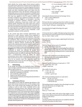
Pressure Applied to Engine Blower is 725 PSI 1. And many more 11. Design of Crank Pin Torque at Crank Pin Tcr P602πN 74560 2π100 7114 N-m Force at Crank Pin Fcr Torque crank radius 71141000 75 948 N Max Force at Crank Pin Fcrm Fcr IF 9482 1896 N Diameter of Crank Pin sqrt4Fπτ sqrt41896 π50 7 mm 8 mm standard size pin.
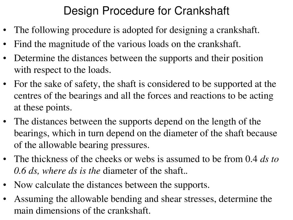
P 3766 MPa Piston pin End. Know more about crankshaft grinding and crankshaft repairs - There are numerous groups in the business that offers crankshaft repairs and producing aids. Design Procedure for Crankshaft The following procedure may be adopted for designing a crankshaft.
Daihatsu 5DK-20 Engine Crankshaft Repair - RA Power Solutions was approached by a leading shipping company regarding problem faced by them in the crankshaft of Daihatsu 5DK-20 Auxiliary Engine. PCY Last modified by. 91-1244378292 4251615 Email ID.
Take the best that exists and make it better. Simulation inputs are taken from the engine specification chart. Quick intro to Crankshaft vibrations.
PowerPoint PPT presentation free to view Automotive Forging Market. Improvement in engine will. A three-dimension model of diesel engine crankshaft is created using Pro-E software.
Jaimin Brahmbhatt Design And Analysis Of Crankshaft For Single Cylinder 4-Stroke Deisel Engine International Journal of Advanced Engineering Research and Studies- E-ISSN2249 8974 2. Design of an Engine Crankshaft 1. Dell Created Date.
ENGINE BLOCK Cast in one piece. Assistant Professor Guru Nanak Institute of T echnology Hyderabad T. Bell 47G-2 Agricultural aerial application Part 137 Part 137 flight with 540 rotorcraft hour pilot.
Design and Validation of a Crankshaft 4. CRANKSHAFT Singular costliest item in diesel engine. P 415 MPa Piston pin End.
Srihari Shaik Himam Saheb S. Converted to mechanical power on to the crankshaft and part of it is wasted as heat losses through exhaust gases and heat transfers to the surroundings. Failure of the tailrotor drive system involved fatigue fracture of the drive gear shaft.
Crankshaft is one of the critical component for the effective and precise working of the internal combustion engine. After design and analysis of the engine blower the result found from the ansys software are as follows. Finite element analysis for the crankshaft was conducted under extreme operation conditions and stress distribution of the crankshaft was presented.
P 6998 MPa. 41 Figure 213 Stress prediction of crankshaft using a neural network structure Shiomi and Watanabe 1995. Torsional Vibration in Crankshafts - Free download as Powerpoint Presentation ppt PDF File pdf Text File txt or view presentation slides online.
Accurate stresses and deformation are critical input to fatigue analysis and optimization of the crankshaft. Design and development of crankshaft is major issue in industry because it is main power transmitting element. 91 9582647131 Tel No.
Since the analysis is linear and elastic for static analysis the stress displacement and. 42 Figure 215 Solid element model of a crankshaft Payer et al 1995. This project aims to determine.
DESIGN AND ANAL YSIS OF CRANKSHAFT FOR 4-. We performed dynamic analysis of the crankshaft which result shows more realistic whereas static analysis provides an overestimate results. Yu Ding and Xiaobo Li2011 Crankshaft Strength Analysis of a Diesel Engine Using Finite Element Method Asia-Pacific Power and Energy Engineering.
The crank stress change model and the crank stress biggest hazard point were found by using finite element analysis and the improvement method for the crankshaft structure design was given. When it does not exist design it - Sir Henry Royce 3. AVINASH KUMAR 3686009 T R SAI.
P 7717 MPa. Design and Analysis of an IC Engine Piston and Piston Rings by using Three Different Materials 22 Piston rings commonly used on small engines include the compression ring wiper ring and oil ring. Analysis results so we can say that Dynamic FEA is a good tool reduce costly experimental work.
This project aims at designing a connecting rod with standard dimensions of a stock one in CREO 30 software and analyze the design using designing software ANSYS. Determine the distances between the supports and their position with respect to the loads. First of all find the magnitude of the various loads on the crankshaft.
41 Figure 214 Flow-chart for transient stress analysis of crankshaft Payer et al 1995. Working Model Slider Crank Solid Works 3D 2005. Mechanical and biomechanical analysis of a linear piston design for angular-velocity-based orthotic control.
Fatigue origin was adjaced to a key slot and progressed over 90 of the shaft cross section prior to seperation. 21 st March 2011 Sakib Sarker Darlington Midrange Technical Operations MTO 2. Project Carried Out by.
Global Industry Analysis 2013 - 2017 and Opportunity Assessment. DETAILED VIEW OF THE COMPONENTS 1.

Mechanical Design Of Engine Parts Ppt Download

Design And Analysis Of Crankshaft For Internal Combustion Engine
2
Design And Analysis Of Crankshaft For Internal Combustion Engine
Mechanical Design Of Engine Parts Ppt Download
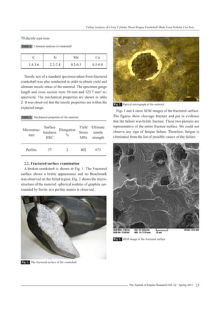
Crankshaft Fatigue

Design Of An Engine Crankshaft
Design And Analysis Of Crankshaft For Internal Combustion Engine
0 komentar
Posting Komentar